cat ~/notes/touch-ot.md
building a small ot/ics lab with a raspberry pi and esp32
[id]building a small ot/ics lab with a raspberry pi and esp32

I needed a network full of OT/ICS devices to test a security scanner. Real PLCs, gateways, and field devices get expensive quickly, so I built the smallest useful lab from a raspi 5 and an esp32.
The raspi impersonates several industrial systems at once. The esp32 provides the physical side: a temperature sensor, relays, and its own Modbus TCP server over Ethernet.
The point was not to reproduce a plant. It was to make protocol discovery fail in the same ways it does against real devices.
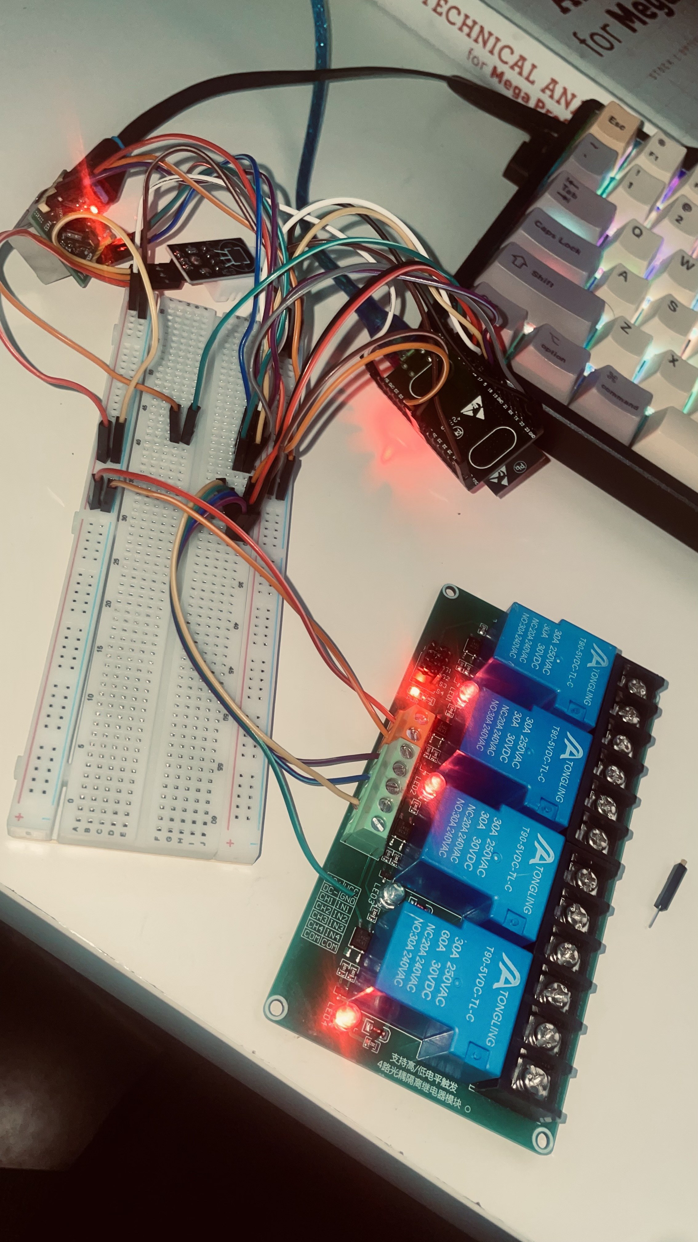
The lab in one table
I bought the parts from a local electronics store in Indonesia:
| item | qty | price |
|---|---|---|
| esp32 devkitc v4 wroom-32d + micro USB | 1 | 81k |
| w5500 ethernet LAN TCP/IP module | 1 | 65k |
| relay module 5V 4ch 30A optocoupler | 1 | 110k |
| dht22 am2302 temperature and humidity sensor | 1 | 22k |
| LCD 1602 I2C green backlight | 1 | 27k |
| RGB LED 5mm 3-color | 5 | 3k |
| breadboard 830p | 1 | 12k |
| 15cm dupont jumper wire pack | 1 | 36k |
The subtotal was 359k IDR. Discounts and shipping brought the final price to 314k IDR. I already owned the raspi.
One raspi, several industrial identities
The raspi runs three small protocol servers:
- Modbus TCP on port
502, with PLC holding registers and coils - Siemens S7 on port
102, emulating a Siemens CPU 315-2 PN/DP through snap7 - BACnet/IP on port
47808, emulating a building automation controller through bac0
I added mosquitto as an MQTT broker on port 1883 and snmpd on port 161.
Every component runs as a systemd service.
port 22    - SSH
port 102   - Siemens S7
port 161   - SNMP
port 502   - Modbus TCP
port 1883  - MQTT
port 5353  - mDNS
port 47808 - BACnet/IP
From the scanner’s perspective, one raspi now looks like a small rack of industrial equipment. That is useful because scanners cannot assume one host has one protocol or one identity.
Giving the lab physical I/O
The esp32 connects to a w5500 Ethernet module over SPI. A dht22 supplies real temperature and humidity values, while a four-channel relay gives the scanner physical outputs to detect and control.
The wiring uses female-to-female jumpers. The esp32 devkitc is wide enough to cover every breadboard row from A through J, so the breadboard only distributes power and the controller sits beside it.
Two servers on one microcontroller
The first firmware used the Arduino Ethernet library for the w5500. An HTTP server worked. A Modbus server worked. Running both together crashed the esp32.
The library was not thread-safe under FreeRTOS, which allowed both server tasks to collide on the SPI bus.
I replaced it with ETH.h, the native ESP-IDF w5500 driver backed by lwIP.
Both servers came up without the SPI race.
The firmware exposes:
- a Modbus TCP server on port
1234 - an HTTP status page on port
1111 - temperature and humidity readings from the dht22
- relay control over Modbus or HTTP
- MEI with function code
0x2b - Report Slave ID with function code
0x11 - Modbus exception responses for unsupported function codes
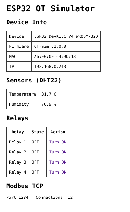
Flashing the firmware on Ubuntu
I used the Arduino IDE with an upload speed of 115200.
On Ubuntu, brltty can claim the cp210x USB serial device before the IDE connects. Stopping and masking its udev service released the port:
sudo systemctl stop brltty-udev
sudo systemctl disable brltty-udev
sudo systemctl mask brltty-udev
Checking each protocol directly
The examples below use documentation-only IP addresses, not addresses from the lab.
Modbus to the esp32
from pymodbus.client import ModbusTcpClient

client = ModbusTcpClient('192.0.2.10', port=1234)
client.connect()
result = client.read_holding_registers(address=0, count=3)
print(f'temp: {result.registers[0] / 10.0} C')
# 31.9 C - real data from the dht22
S7 to the raspi
import snap7

client = snap7.Client()
client.connect('192.0.2.20', 0, 1)
info = client.get_cpu_info()
# CPU 315-2 PN/DP
BACnet to the raspi
import socket

sock = socket.socket(socket.AF_INET, socket.SOCK_DGRAM)
sock.settimeout(2)
packet = bytes([0x81, 0x0a, 0x00, 0x08, 0x01, 0x00, 0x10, 0x08])
sock.sendto(packet, ('192.0.2.20', 47808))
data, addr = sock.recvfrom(1024)
# 21 bytes - BACnet I-Am response
Each protocol gave the scanner a different identity and response shape.
The first Modbus scan failed
The scanner tried MEI, Report Slave ID, holding registers, and coils against the esp32. Every probe failed.
The firmware did not return a Modbus exception for an unsupported function code. It stayed silent and closed the connection.
The scanner tried MEI first, waited for a timeout, lost the socket, then hit a broken pipe on every later request. One unsupported probe poisoned the entire fingerprint sequence.
The fix belonged on both sides:
- the firmware now returns an exception with
function_code | 0x80 - the scanner reconnects when a device drops the socket
After those changes, both hosts identified themselves:
esp32:
  method: report_slave_id
  slave_id: ESP32-IoT-Controller-v1.0.0

raspi:
  method: mei
  manufacturer: RaspberryPi-OT-Sim
  label: RPi5-PLC
  firmware_version: 1.0.0
The lab exposed a useful scanner rule: a failed optional probe must not prevent later probes from running.
The crash on the SPI bus
The original Ethernet stack failed with:
assert failed: xQueueSemaphoreTake queue.c:1709FreeRTOS preemption let both server tasks access an unprotected SPI path.
Moving to the native ETH.h driver removed that race and kept HTTP and Modbus alive together.
Inspecting the wire
Wireshark can decode every protocol in the lab.
The esp32 runs Modbus on port 1234 instead of the standard port, so Wireshark needs an explicit decoder mapping: Analyze, Decode As, TCP port 1234, then Modbus/TCP.
modbus  - Modbus TCP
s7comm  - Siemens S7
bacnet  - BACnet/IP
mqtt    - MQTT
This small setup exercises more than happy-path handshakes. It covers multiple protocols on one host, physical Ethernet I/O, unsupported function codes, dropped connections, reconnect behavior, and sensor values that actually change.
That is enough realism to make a scanner reveal bad assumptions before it reaches an industrial network.
The code is available at github.com/zsbahtiar/touch-ot.